
Automating Your Grow Room with Raspberry Pi or Arduino
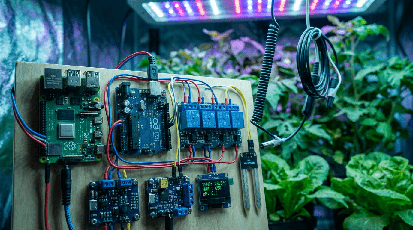
Off-the-shelf environmental controllers for grow tents are convenient but limited. They control temperature and humidity within a fixed range, log data to a proprietary app, and cost between one hundred and five hundred dollars. For growers who want granular control over every variable, integration with home automation systems, or the ability to build custom logic that no commercial controller supports, a microcontroller-based automation system built with Raspberry Pi or Arduino is the solution.
A Raspberry Pi or Arduino-based grow controller can monitor temperature, humidity, VPD, light intensity, CO2 concentration, nutrient solution pH and EC, water temperature, and reservoir level. It can control exhaust fans, intake fans, humidifiers, dehumidifiers, heaters, chillers, pumps, and lights based on configurable setpoints, time schedules, and even predictive algorithms that anticipate environmental changes before they happen. The system can log data to a local database or cloud service, send alerts to your phone, and be controlled remotely from anywhere.
This guide covers the hardware and software required to build a fully automated grow room controller, sensor selection and wiring, relay control for AC devices, programming the control logic in Python or C++, data logging and visualization, and common pitfalls to avoid. The system described costs approximately one hundred to two hundred dollars in components and requires basic soldering and programming skills to assemble.
The Lab's Verdict
Use a Raspberry Pi for any project that needs network connectivity, data logging, or remote control. Use an Arduino for simple, dedicated control loops that must run reliably 24/7 without network dependencies. For a complete grow room automation system, the best approach is a hybrid: Arduino microcontrollers handle real-time sensor reading and relay control at the device level, while a Raspberry Pi serves as the central hub that aggregates data, runs the control logic, and provides the web interface. This architecture combines the reliability of Arduino with the connectivity of Raspberry Pi. We provide complete wiring diagrams and code examples for this hybrid system below.
Raspberry Pi vs Arduino: Choosing the Right Platform
Raspberry Pi is a single-board computer that runs a full Linux operating system. It has USB ports, HDMI output, built-in WiFi and Bluetooth, GPIO pins for connecting sensors and relays, and the ability to run Python, Node.js, or any programming language that runs on Linux. The Pi is the right choice when your project needs network communication, a web interface, file storage, or complex data processing. The Raspberry Pi 4 or Raspberry Pi 5 with 4GB of RAM is sufficient for any grow room automation project.
Arduino is a microcontroller board that runs a single program in a loop. It has no operating system, no network stack, and no file system in its basic form. It consumes approximately fifty milliamps of current compared to the Pi's five hundred to one thousand milliamps. Arduino boots instantly when power is applied and runs indefinitely without crashing, rebooting, or requiring software updates. The Arduino Uno R3 or Arduino Mega 2560 are the standard choices for grow room sensor and relay projects.
The fundamental difference is that Raspberry Pi is a general-purpose computer that can do many things but is vulnerable to SD card corruption, power supply issues, and operating system crashes. Arduino is a dedicated controller that does one thing reliably but cannot handle complex tasks like serving a web page or storing large amounts of data. For a grow room controller that runs unattended for months, the Arduino's reliability advantage is significant.
Our recommended hybrid architecture uses an Arduino Mega connected to all sensors and relays through a custom shield or wiring harness. The Arduino runs the real-time control loop that reads sensors and switches relays every one to five seconds. It communicates with a Raspberry Pi over USB serial, sending sensor readings and receiving setpoint updates. The Raspberry Pi runs a Python or Node.js application that logs data to a SQLite database, serves a local web dashboard, and sends push notifications through Telegram or Pushover. If the Raspberry Pi crashes or loses power, the Arduino continues running with its last received setpoints, maintaining environmental control without interruption.
Platform Comparison
| Feature | Raspberry Pi 4/5 | Arduino Uno/Mega |
|---|---|---|
| Processor | ARM Cortex-A72/A76, 1.8-2.4 GHz | ATmega328P/2560, 16 MHz |
| RAM | 1-8 GB | 2-8 KB |
| Power consumption | 3-8 watts | 0.3-0.5 watts |
| Boot time | 20-40 seconds | Instant |
| Network connectivity | Built-in WiFi + Ethernet | Requires Ethernet shield or ESP32 |
| Analog inputs | None (requires ADC chip) | 6-16 built-in |
| Programming language | Python, Node.js, C++, any | C++ (Arduino IDE) |
| Ideal role in grow room | Data logging, dashboard, alerts | Real-time sensor reading, relay control |
| Cost | $35-75 | $10-40 |
Essential Sensors for Grow Room Automation
The sensors you choose determine what your controller can measure and therefore what it can control. Each sensor type has specific wiring requirements, communication protocols, and accuracy characteristics that affect system design.
Temperature and humidity. The DHT22 is the most widely used temperature and humidity sensor for DIY grow controllers. It measures temperature from minus 40 to 80 degrees Celsius with plus or minus 0.5 degree accuracy, and humidity from zero to one hundred percent with plus or minus two percent accuracy. The DHT22 uses a single digital data pin and communicates with a custom one-wire protocol. It is inexpensive, widely available, and has good long-term stability. The DHT11 is cheaper but less accurate and should be avoided for grow room applications. The BME280 sensor provides temperature, humidity, and barometric pressure with higher accuracy than the DHT22 and uses I2C communication, which allows multiple sensors on a single bus.
Light intensity. The TSL2591 high-dynamic-range light sensor measures visible and infrared light across a range of 0.0001 to 88,000 lux, which covers the full range of indoor grow light intensities from seedling to full flower. It communicates over I2C and can be placed at canopy level inside the grow tent. The sensor returns data in lux, which can be converted to approximate PPFD using a calibration factor for your specific light spectrum, though for accurate PPFD measurements a dedicated quantum sensor such as the SQ-120 is recommended.
CO2 concentration. The MH-Z19B NDIR CO2 sensor measures carbon dioxide concentration from 400 to 5000 parts per million with an accuracy of plus or minus 50 ppm plus five percent of the reading. It uses UART serial communication and requires a five-volt power supply. The sensor has automatic baseline calibration that assumes the sensor is exposed to fresh outside air at 400 ppm every 24 hours. In a sealed grow room where CO2 levels are always elevated, this baseline calibration drifts and should be disabled, with manual calibration performed using a reference gas every three months.
pH and EC. Analog pH and EC sensors from Atlas Scientific are the gold standard for DIY hydroponic monitoring. The Atlas Scientific pH probe with the EZO pH circuit provides readings with plus or minus 0.002 pH accuracy and communicates over I2C or UART. The EZO EC circuit measures conductivity from 0.07 to 500,000 microsiemens with automatic temperature compensation. These sensors require calibration before first use and periodic recalibration every two to four weeks. The probes cost approximately sixty to eighty dollars each.
Water temperature and level. A DS18B20 waterproof temperature sensor measures water temperature from minus 55 to 125 degrees Celsius with plus or minus 0.5 degree accuracy. It uses a one-wire digital protocol and multiple sensors can share a single data pin. Water level can be monitored with a simple float switch or an ultrasonic distance sensor such as the HC-SR04 mounted above the reservoir to measure water surface distance. The ultrasonic sensor is non-contact and does not require sterilization between grow cycles.
Relay Control for AC Devices
Sensors give your controller information. Relays give your controller the ability to act. A relay is an electrically operated switch that allows a low-voltage microcontroller signal to control a high-voltage AC device such as a fan, pump, light, or heater. Choosing the correct relay module and wiring it safely is the most critical part of building a grow room controller.
The standard relay module for Arduino and Raspberry Pi projects is the two-channel or four-channel relay board with optocoupler isolation. Optocouplers provide electrical isolation between the microcontroller and the AC high-voltage side, protecting the microcontroller and the user from electrical shock if the AC side fails. Each relay channel has three screw terminals labeled common, normally open, and normally closed. For grow room applications, the normally open configuration is used: the AC device is off when the relay is not energized and turns on when the microcontroller activates the relay.
Relay modules are available with mechanical relays or solid-state relays. Mechanical relays use a physical electromagnetic switch that produces an audible click when activated. They are inexpensive, handle high currents, and are suitable for devices that switch on and off infrequently. Solid-state relays use semiconductor switching with no moving parts, produce no audible noise, and last longer in applications with frequent switching cycles. For exhaust fans and lights that switch a few times per day, mechanical relays are adequate. For pumps that cycle every 15 to 30 minutes, solid-state relays are recommended.
Each relay channel is rated for a maximum current in amps. A standard exhaust fan draws 1 to 3 amps at 120 volts. A dehumidifier draws 3 to 6 amps. A grow light draws 2 to 5 amps depending on wattage. Sum the current draw of all devices that may be on simultaneously and ensure that the total does not exceed the relay module rating and the circuit breaker rating for the outlet. A 10-amp relay module is sufficient for a typical 4x4 grow tent setup with four to six controlled devices.
Wiring safety is non-negotiable. Use wire nuts or Wago connectors for all AC connections. Enclose the relay module and all AC wiring in a grounded metal or polycarbonate electrical enclosure. Label each relay channel and its corresponding AC device on the enclosure exterior. Install a master switch and fuse or circuit breaker on the AC input side so the entire system can be disconnected for maintenance. Never work on AC wiring while the system is plugged in.
Programming the Control Logic
The control logic is the brain of your automation system. It reads sensor data, compares readings against setpoints, and activates or deactivates relays to maintain target conditions. The logic must handle normal operation, sensor failures, and edge cases such as power outages and network disconnections.
The simplest control logic is hysteresis-based setpoint control with a dead band. For temperature, you define a target of 75 degrees Fahrenheit with a dead band of plus or minus two degrees. The controller turns on the exhaust fan when temperature reaches 77 degrees and turns it off when temperature falls to 73 degrees. The dead band prevents rapid on-off cycling that wears out relays and creates temperature oscillations. Each controlled variable has an independent hysteresis control loop that runs every one to five seconds.
VPD-based control is more advanced. Instead of controlling temperature and humidity independently, the controller calculates VPD from both sensors and activates whichever device, fan, heater, humidifier, or dehumidifier, that moves VPD toward the target band. VPD-based control requires careful prioritization logic to prevent conflicts. For example, if the VPD is too high, the controller should increase humidity before decreasing temperature because humidity changes affect VPD more directly and can be achieved with less energy.
A timer-based override system adds fail-safe behavior. Each relay has a maximum on-time and minimum off-time. If the exhaust fan has been running for more than 30 minutes continuously, the controller turns it off for five minutes regardless of temperature to prevent motor overheating. If the humidifier has been running for more than 15 minutes without increasing humidity by at least two percent, the controller flags a possible water reservoir empty condition and sends an alert.
Sensor validation is essential. A failed sensor can cause the controller to make incorrect decisions. Implement a sanity check for each sensor: temperature readings above 120 degrees Fahrenheit or below 20 degrees are flagged as invalid. Humidity readings of exactly zero percent or one hundred percent that persist for more than 15 minutes indicate a stuck sensor. When a sensor reading is invalid, the controller should maintain the last valid relay state and send an alert rather than taking corrective action based on bad data.
Data Logging and Visualization
Data logging transforms your controller from a simple thermostat into a analytical tool that helps you understand your grow environment over time. A Raspberry Pi running InfluxDB and Grafana provides enterprise-grade time-series data storage and visualization for a home grow room.
InfluxDB is a time-series database optimized for storing sensor data at high write frequencies. Each sensor reading is stored as a data point with a timestamp, sensor name, and value. The database automatically manages data retention, deleting data older than a configurable period. A 30-day retention period at five-second logging intervals produces approximately 1.5 million data points and consumes approximately 200 megabytes of storage, which is well within the capacity of a 32-gigabyte SD card.
Grafana connects to InfluxDB and renders dashboards with real-time charts, gauges, and alerts. A typical grow room dashboard has a row for each controlled variable: temperature and humidity with a combined chart that shows both values and the calculated VPD, a relay state panel that shows which devices are currently active, a history panel showing the previous 24 hours of each variable, and a alerts panel listing recent out-of-range events. Grafana dashboards can be accessed from any device on the local network through a web browser.
Alerting is the most practically useful feature of a data-logging system. Configure Grafana to send alerts when temperature exceeds 85 degrees Fahrenheit, humidity exceeds 70 percent during flower, or VPD falls outside the target band for more than 30 consecutive minutes. Alerts can be sent through email, Telegram, Pushover, or webhook to a smart home hub. The alert message should include the current reading, the threshold that was exceeded, and the duration of the exceedance.
Build Checklist
- Stage 1 — Sensors: DHT22 (temp/RH), TSL2591 (light), MH-Z19B (CO2), DS18B20 (water temp), float switch (water level).
- Stage 2 — Control: 4-channel relay module with optocoupler isolation. Mechanical relays for lights and fans, solid-state for pumps.
- Stage 3 — Microcontroller: Arduino Mega for real-time loop. Raspberry Pi 4 for logging and dashboard.
- Stage 4 — Software: Arduino sketch with hysteresis control loops. Python script on Pi for serial communication and InfluxDB write.
- Stage 5 — Dashboard: Grafana with InfluxDB data source. Telegram bot or Pushover for alerts.
Frequently Asked Questions
Do I need to know programming to build this system?
Basic familiarity with Python or C++ is required. The control logic is simple, and extensive example code is available online. If you are new to programming, start with a single sensor and a single relay, get that working, then expand. Arduino programming is easier to learn than Raspberry Pi programming because the execution environment is simpler.
Can I use WiFi instead of USB serial for communication?
Yes. Add an ESP32 or ESP8266 WiFi module to the Arduino for wireless communication with the Raspberry Pi. WiFi introduces latency and connection reliability concerns, so the Arduino must still be programmed to run independently if the WiFi connection drops. USB serial is more reliable and preferred for permanent installations.
How do I power the Arduino and Raspberry Pi inside the grow tent?
Place the electronics enclosure outside the grow tent to protect it from high humidity. Run sensor cables through a sealed cable port into the tent. The Raspberry Pi requires a 5-volt 3-amp USB-C power supply. The Arduino requires a 7-to-12-volt DC power supply or USB power from the Raspberry Pi.
What happens if the Raspberry Pi SD card corrupts?
If the Arduino is programmed with the hybrid architecture described above, it continues running with its last received setpoints. Data logging stops until the Raspberry Pi is restored. Use a high-endurance SD card rated for continuous write operations, and back up the Grafana and InfluxDB configuration to a second location weekly.
Can this system control a variable-speed fan?
Yes, with an additional component. A standard relay only provides on-off control. For variable-speed control, add a PWM Fan Controller module or a solid-state relay with phase-angle control that accepts a 0-to-10-volt analog signal from the Arduino. The Arduino generates a PWM signal that is converted to the 0-to-10-volt control signal through a simple RC filter circuit.
How accurate are DIY pH and EC sensors for hydroponics?
Atlas Scientific probes with the EZO circuits provide accuracy comparable to consumer-grade handheld meters when properly calibrated. The pH probe requires calibration at pH 4.0, 7.0, and 10.0 before first use and recalibration every two to four weeks. The EC probe requires a single-point calibration with a known standard solution. Drift between calibrations is typically less than 0.1 pH and 50 µS per week.
Is a Raspberry Pi 5 worth the extra cost over a Pi 4?
For grow room automation, the Pi 4 with 4GB RAM is sufficient and the Pi 5 offers no practical advantage. The Pi 5 has a faster processor and slightly lower power consumption, but the control loop and data logging tasks do not benefit from the additional processing power. Save the difference and spend it on a better sensor or relay module.
Start Building Your Automated Grow Room
Three entry points depending on your technical comfort level.
The Beginner Builder
Start with a single Arduino Uno, DHT22 sensor, and relay module. Build a temperature-controlled exhaust fan. No networking required.
The Intermediate Integrator
Build the hybrid Pi plus Arduino system. Add DHT22, TSL2591, and DS18B20 sensors. Set up Grafana dashboard on local network.
The Advanced Automator
Add pH and EC sensors, CO2 monitoring with variable-speed fan control, VPD-based control logic, and Telegram alerts for out-of-range conditions.
The Lab's Final Analysis
Building your own grow room automation system is not the cheapest or fastest path to environmental control. A commercial controller costs three hundred dollars and works out of the box. A DIY system costs one hundred to two hundred dollars in components and requires ten to twenty hours of assembly, programming, and testing. The advantage of the DIY system is not cost — it is capability and flexibility. No commercial controller offers the ability to integrate a custom CO2 sensor, control a variable-speed fan based on VPD, log data to a local database with 30-second granularity, and send Telegram alerts with custom messages. Those features require a custom solution.
The hybrid Arduino-Pi architecture we recommend provides reliability that a Pi-only system cannot match. The Arduino runs the critical control loop without depending on an operating system, network connection, or SD card. It will continue controlling your environment through power fluctuations, network outages, and SD card corruption events that would disable a Pi-only system. The Pi adds the data logging, dashboard, and alerts that make the system useful for analysis and remote monitoring.
Start small. Build a single temperature control loop with one sensor and one relay. Get that working reliably for one week before adding additional sensors or control loops. Each new component introduces potential failure modes, and adding everything at once makes troubleshooting impossible. A working system with temperature control only is more useful than a broken system with ten sensors and no working relays.
Build the control loop first, then add the dashboard. Test each sensor and relay individually before integrating. Set up alerts before you need them. The goal is a system that runs unattended for months and only contacts you when something needs attention.
More from Lighting & Climate
Keep reading
How to Calculate Electricity Costs for Your Indoor Garden
Explore our comprehensive guide on How to Calculate Electricity Costs for Your Indoor Garden. Part of our technical series on lighting and climate technology, this report covers everything you need to optimize your yield and maintain a healthy grow environment.
LED Grow Light Buying Guide 2026: PPFD, Spectrum, and the Spec Sheets That Lie
How to read a grow-light datasheet, why 'equivalent wattage' is meaningless, and three lights we'd actually buy this year.
Controlling Humidity in Grow Tents: Best Dehumidifiers
Complete guide to dehumidifiers for hydroponic grow tents. Compressor vs desiccant, sizing for 2x2 to 5x5 tents, placement and drainage, product recommendations, and integration with environmental controllers for mold-free harvests.